[No.19] I Want to Use Lots of Sensors and LEDs!
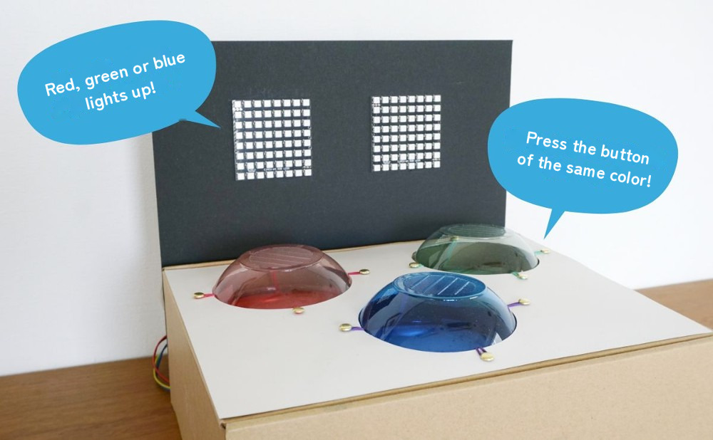
This time, we'll level up a bit and take on making a quick-press game! Until now, we've only used one LED panel or sensor at a time, but now we'll use more of them, and the program gets a little more advanced too. In this lesson, you'll learn how to connect lots of sensors and other parts to SPACEBLOCK at the same time, and we'll go all the way to building the game machine! The game program is in the next lesson, so check it out.
What You Need & Getting Ready
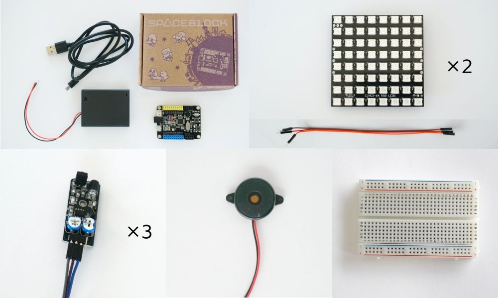
- SPACEBLOCK Standard Package [SPACEBLOCK board, USB cable, battery box]
- Infrared obstacle avoidance sensor module (obstacle avoidance sensor)
- Piezoelectric speaker
- 8×8 RGB LED matrix panel (LED panel)
- Jumper wires [used to extend wires as needed]
- Breadboard*
- A computer for programming
*Breadboards aren't sold on the official SPACEBLOCK website, but you can buy them at many shops as electronics crafting supplies.
Connect the Expansion Parts to SPACEBLOCK
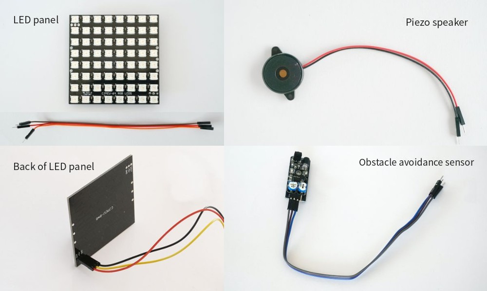
- LED panel (3 wires): 5V power / GND / signal
- Obstacle avoidance sensor (3 wires): 3–5V power / GND / signal
- Piezo speaker (2 wires): GND / signal
*GND (ground) is the minus side, where electricity flows to after coming from the plus side. It's needed to make a path for electricity.
*The piezo speaker is powered through the same wire it uses for signals.
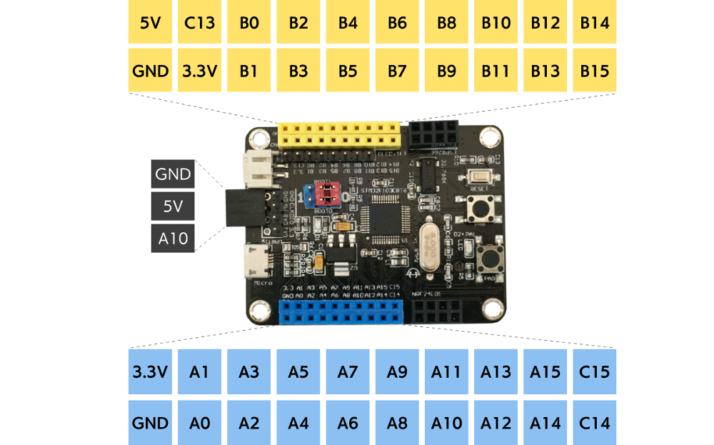
Each part has wires that need to be connected, but SPACEBLOCK only has a limited number of GND and power (5V, 3.3V) pin sockets.Let's check what each of SPACEBLOCK's pin sockets is for
.
As it is, we can't connect all the parts. So we'll use a breadboard to add more pin sockets to connect to. A breadboard is a tool for building circuits easily in electronics projects. This time, we'll use it to add more 5V power and GND connections.
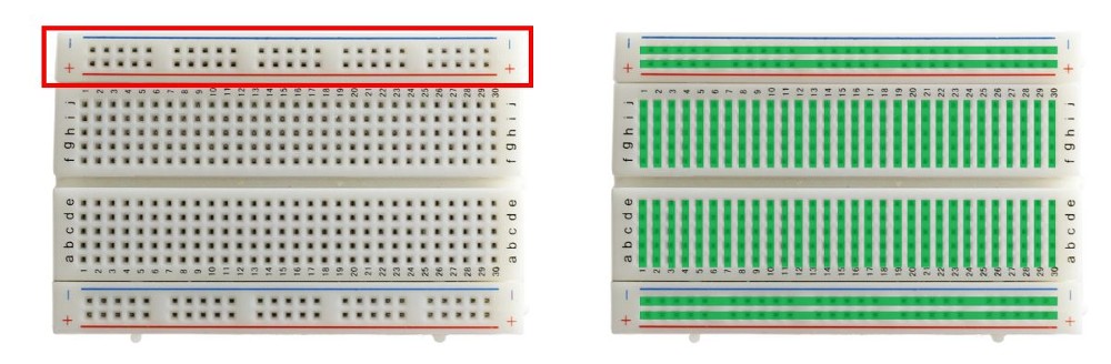
First, use jumper wires to connect SPACEBLOCK's "5V" pin socket to the breadboard's "+" row, and the "GND" pin socket to the "−" row. Now every hole in the breadboard's "+" row works as a "5V" pin socket, and every hole in the "−" row works as a "GND" pin socket.
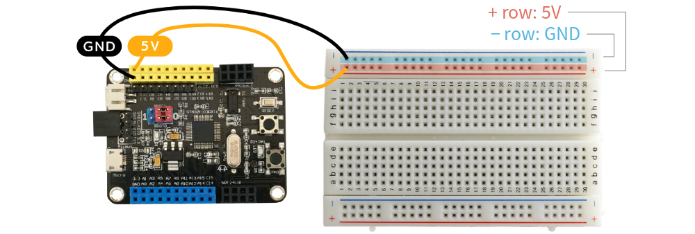
Next, connect the parts that can go straight into SPACEBLOCK. Connect 1 LED panel and the piezo speaker.
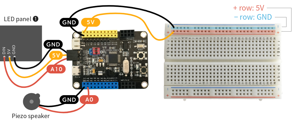
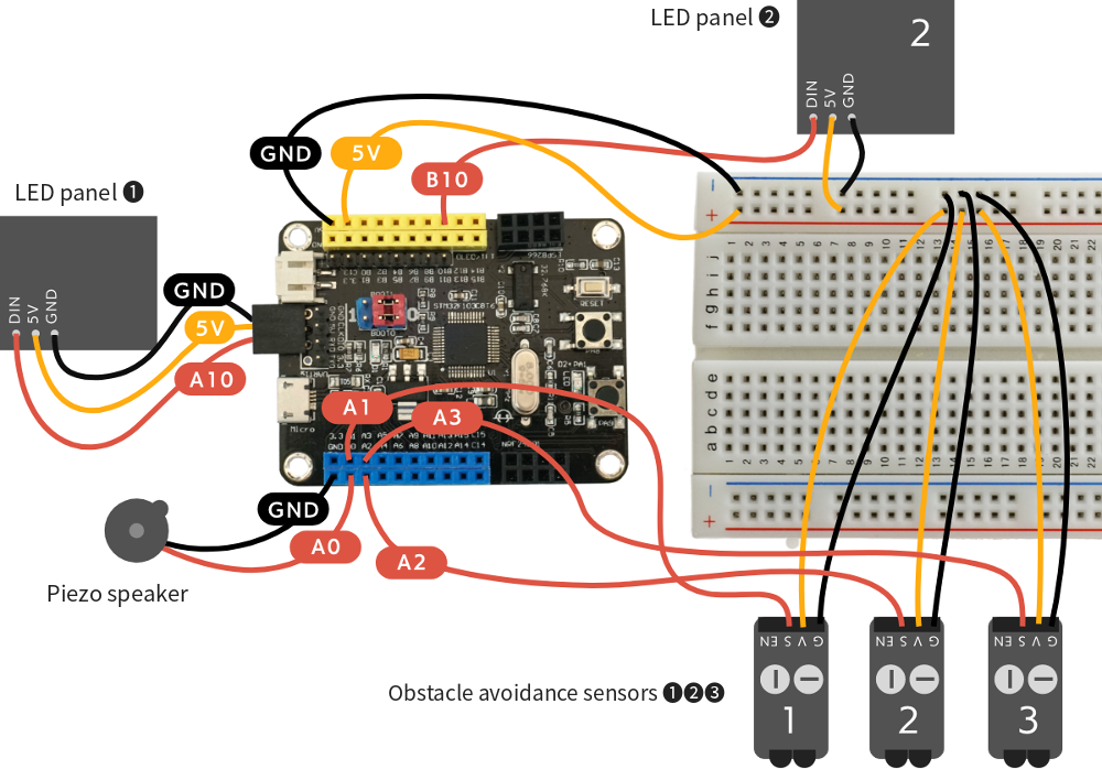
Next, connect the other LED panel and the 3 obstacle avoidance sensors.Connect the GND and power jumper wires to the breadboard, and the signal wires to SPACEBLOCK's pin sockets.
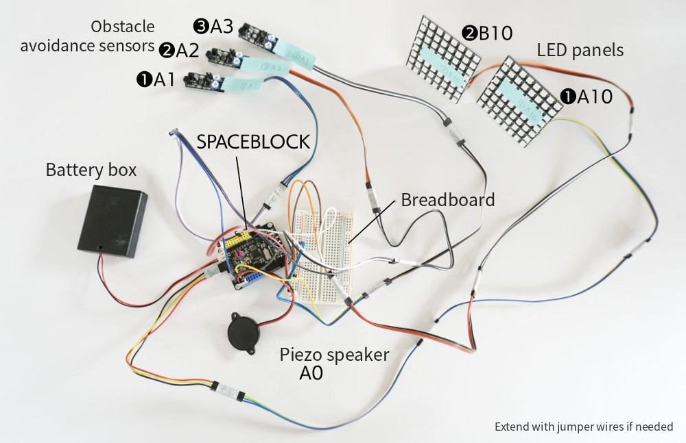
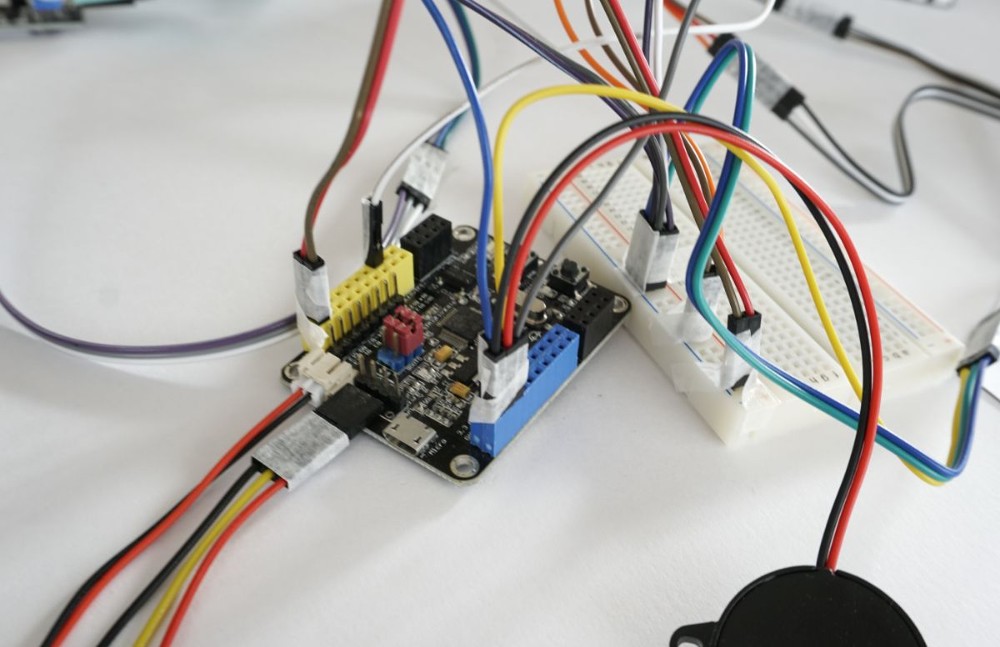
It looks neat in the diagram, but here's a photo of the real connections. It's pretty messy, so it might surprise you a little! But if you check each wire one by one like in the diagram above, you'll be fine.
Check That the Expansion Parts Work
Once you've gotten this far, check that the LED panels, piezo speaker and obstacle avoidance sensors work to make sure everything is connected correctly.
Check the numbers of the pin sockets where each part's signal wire is connected, and run a test program for the connections.
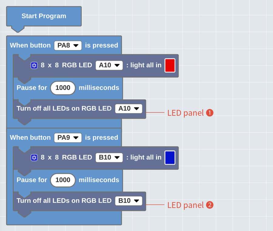
LED panels
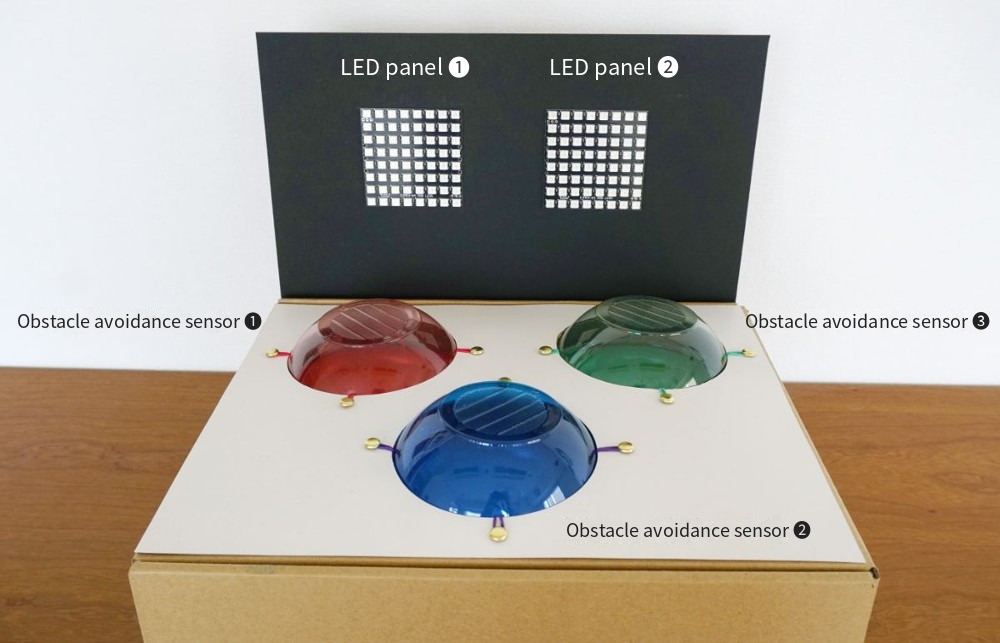
- LED panel ❶ → A10
- LED panel ❷ → B10
[Test program example]
Piezo speaker
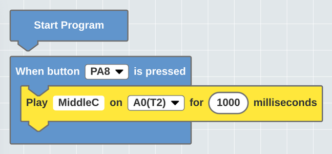
- Piezo speaker → A0
[Test program example]
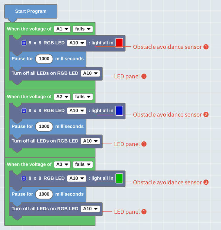
Obstacle avoidance sensors
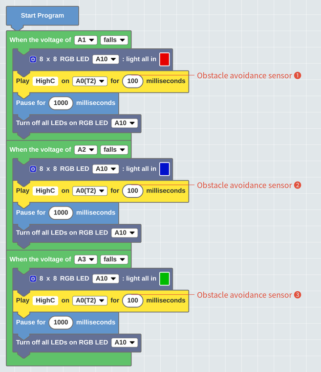
- Obstacle avoidance sensor ❶ → A1
- Obstacle avoidance sensor ❷ → A2
- Obstacle avoidance sensor ❸ → A3
[Test program example]
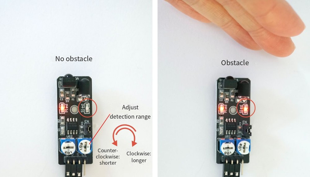
Check the link below for how the obstacle avoidance sensor works and how to adjust its detection distance.
Here's how the "obstacle avoidance sensor" works and how to adjust it!
If something doesn't work, a connection is wrong somewhere. Before building the game machine or programming, make sure everything is connected correctly.
Materials and How the Game Machine Works
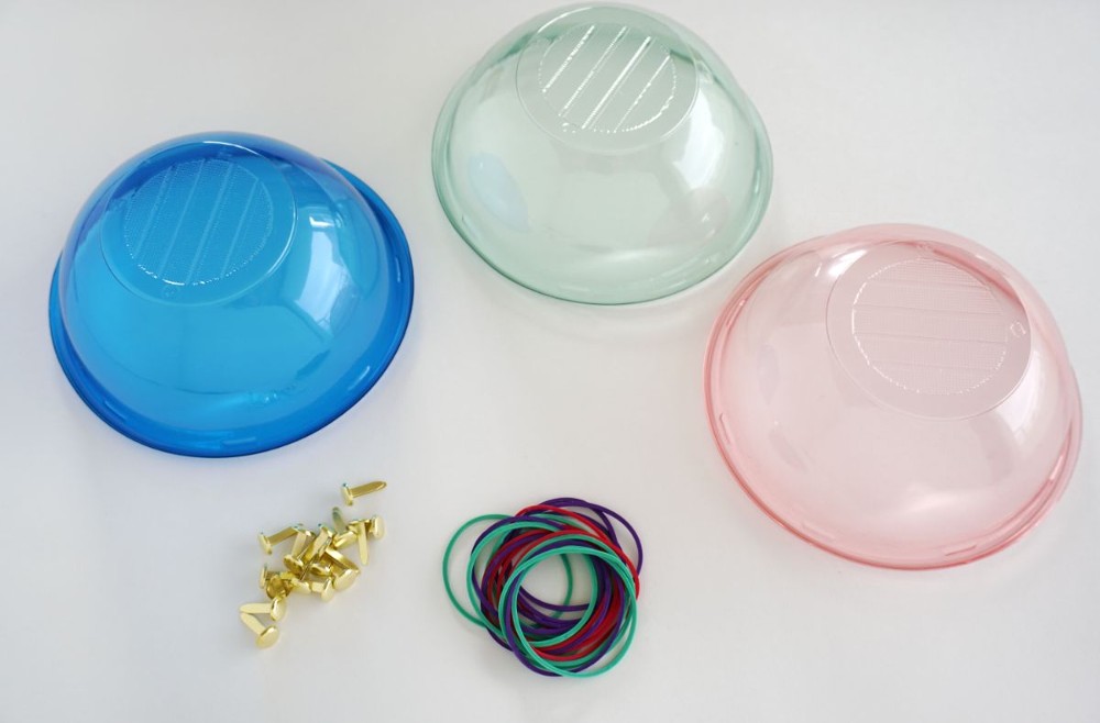
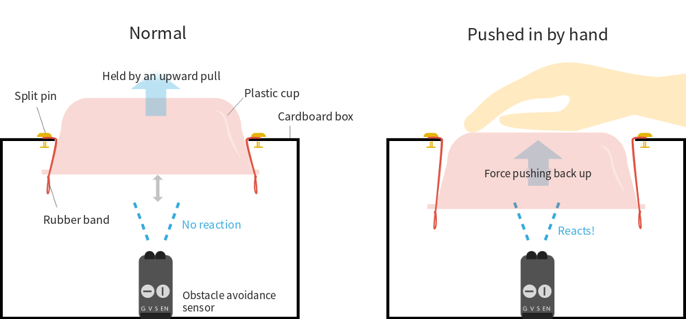
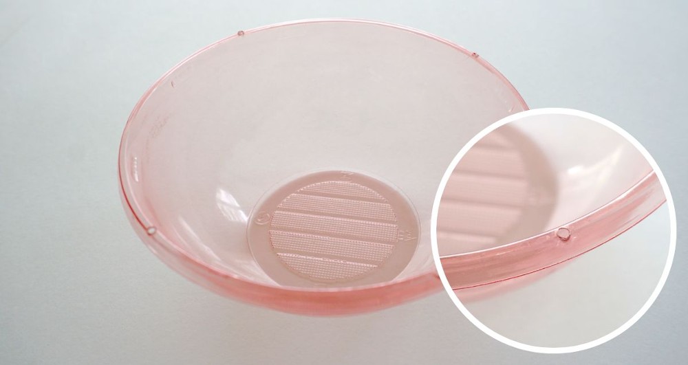
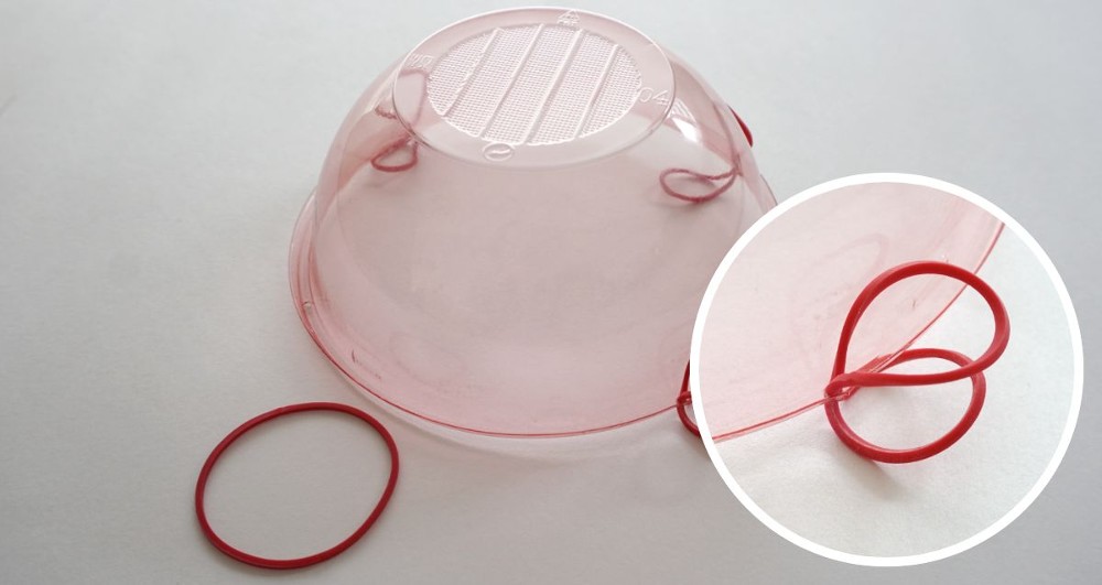
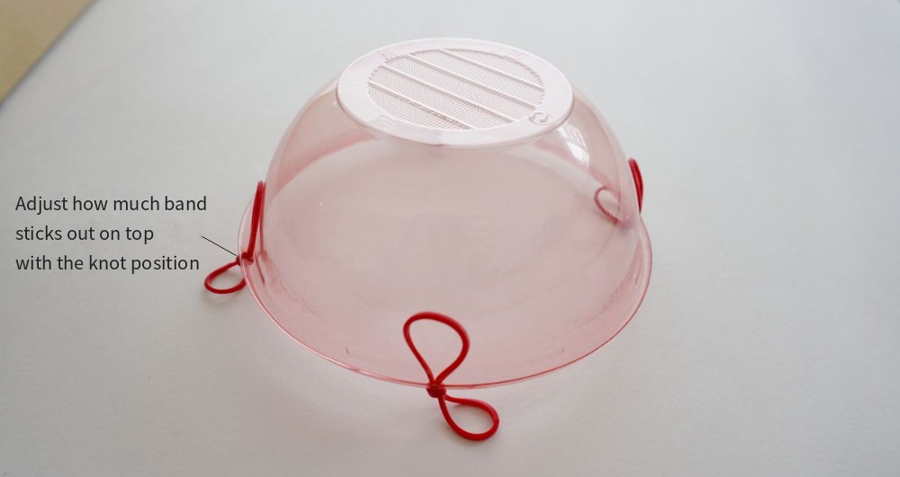
With these materials, you'll make buttons to press. First, let's explain how they work. As shown in the next picture, cut holes in the cardboard box that are a little smaller than the plastic cups, and use split pins and rubber bands to hold each cup so it's pulled up from below.Put an obstacle avoidance sensor inside the box. When you push a button in, the edge of the cup reaches the sensor's detection range and the sensor reacts.
Build the Game Machine: The Craft Part
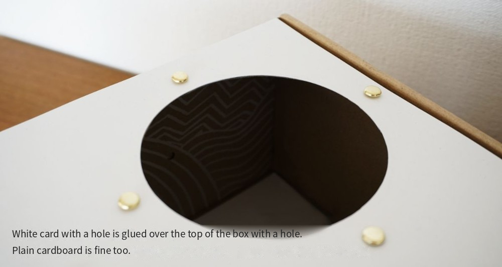
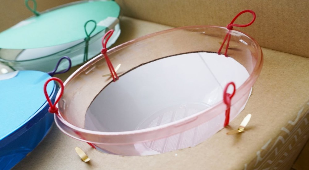
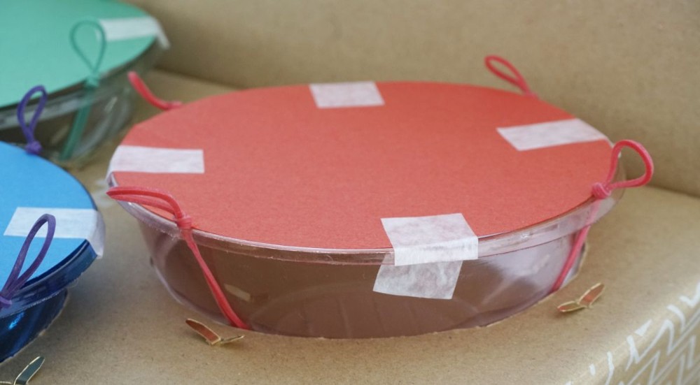
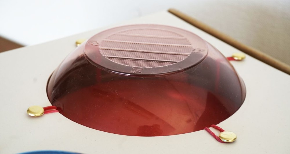
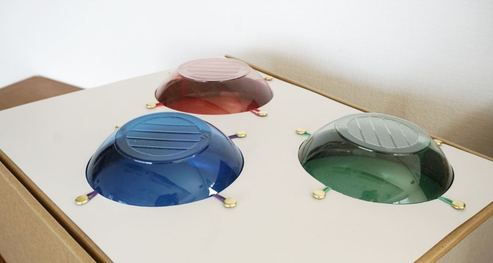
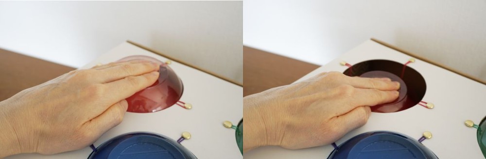
Build the Game Machine: Set Up SPACEBLOCK
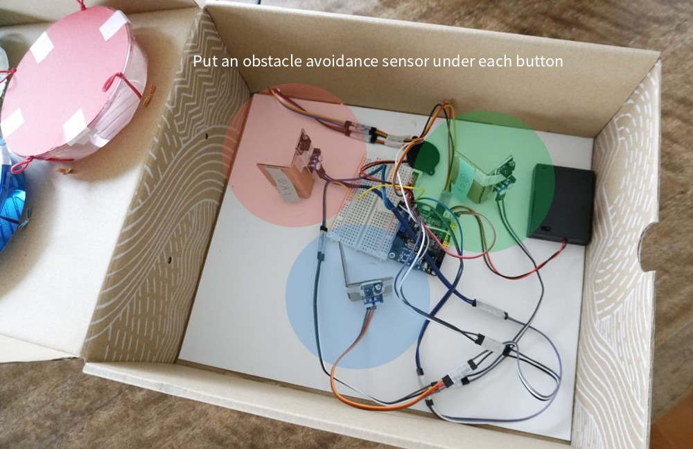
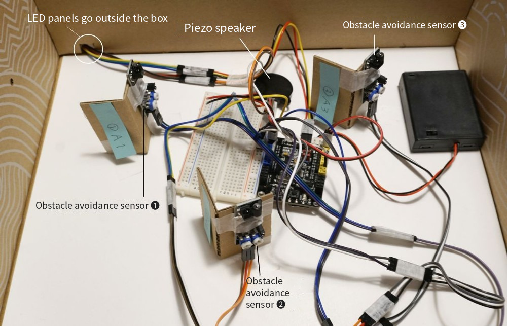
Adjust the height of the obstacle avoidance sensors to match the height of the box and how far the plastic cups sink in.Adjust the detection distance so the sensor doesn't react when the button isn't pressed, and only reacts when it's pushed in.
Here's how the "obstacle avoidance sensor" works and how to adjust it!
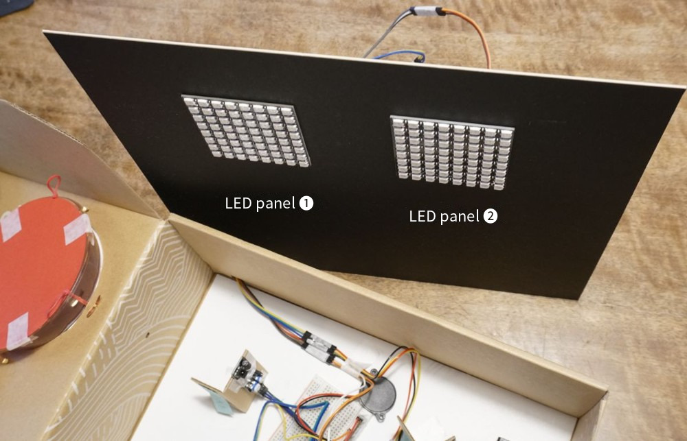
Then put the LED panels outside the box by sticking them onto a board.
Check How It Works with a Test Program!