

[No.6] Add an Output Part: An "Okaeri" Device That Plays Sounds
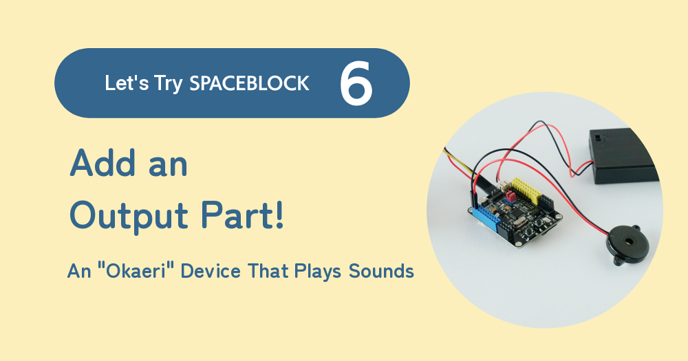
With SPACEBLOCK, the tiny computer for making things, you can add all kinds of parts and create your own features. This time, let's add one output part and make a device that plays sounds. We'll upgrade the "okaeri" (welcome home) display you made in [No.5].
SPACEBLOCK Has Lots of Add-On Parts!
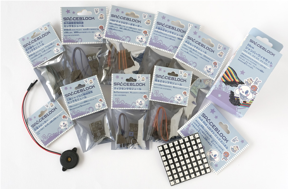
There are parts you can use as all kinds of input and output devices, which makes things even more exciting. For example, you could use an "Ambient Light Sensor Module" as an input to make a device that reacts to brightness, or use a "180° Micro Servo Motor" as an output to make something that turns.
You can buy SPACEBLOCK and its add-on parts on the SPACEBLOCK website, so take a look. This time, we'll use two parts that are already on sale: the "8×8 RGB LED Matrix Panel" (LED panel) and the "Piezoelectric Speaker".
What You Need & Getting Ready
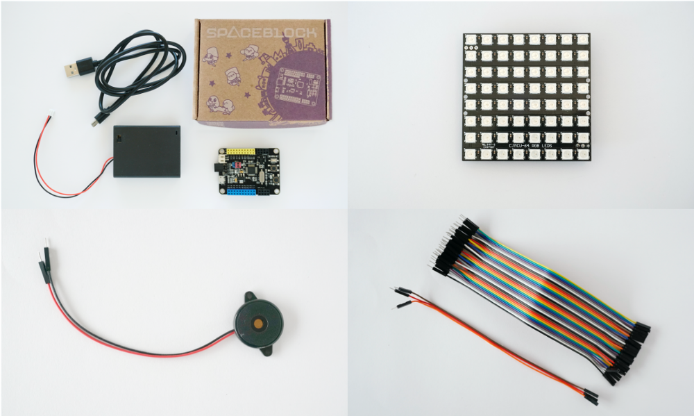
- SPACEBLOCK Standard Package [SPACEBLOCK, USB cable, battery box]
- 8×8 RGB LED Matrix Panel (LED panel)
- Piezoelectric Speaker
- Jumper wires [3 wires, pin header to pin socket]
- A computer for programming
Connect the Add-On Parts to SPACEBLOCK
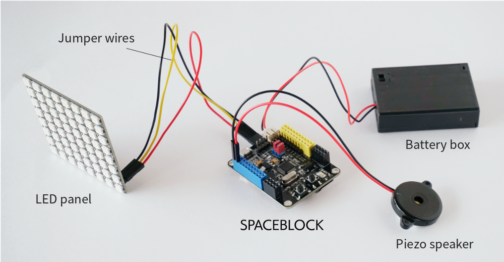
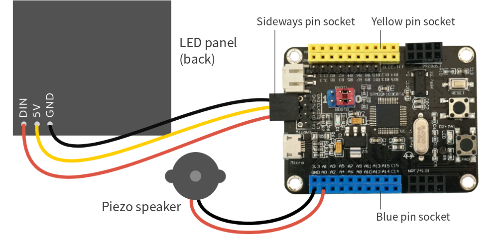
For the details, look at the next picture. You can plug the LED panel straight into the sideways pin socket, but this time we'll use jumper wires to make it easier to handle. Be careful to connect the 3 wires exactly as shown. For the piezo speaker, check the colors of the red and black wires and plug them into the blue pin socket as shown.
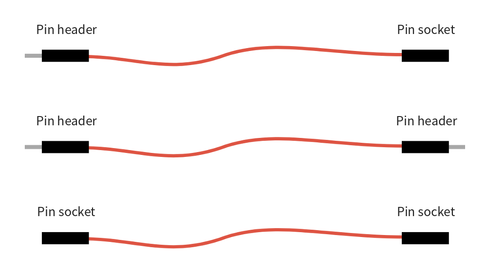
Each end of a jumper wire is either a "pin header" or a "pin socket." There are 3 kinds depending on what's on each end, so choose the one that fits where you want to use it. SPACEBLOCK's "20 cm Jumper Wire Set" comes with 40 of each of the 3 kinds.
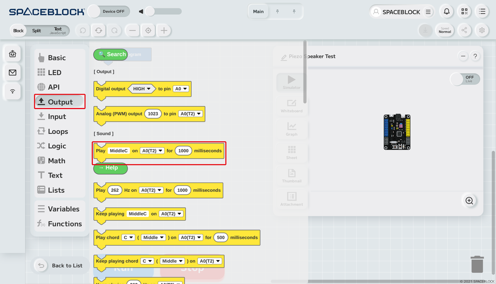
How Do You Program the Piezo Speaker?
Click the pin socket name on the block to see a list, with 4 pin sockets highlighted. To use the piezo speaker, connect the red jumper wire to one of these 4 pin sockets, and the black wire to a pin socket labeled "GND."
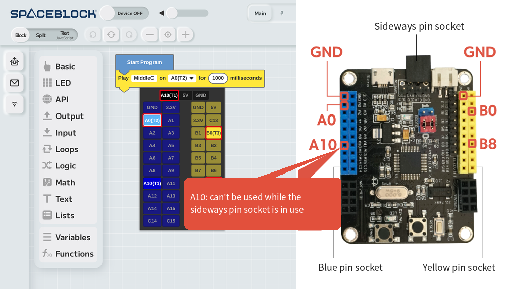
This time we'll use "GND" and "A0 (T2)" on the blue pin socket. Choose "A0 (T2)" in the [Play (Middle C) on (A0 (T2)) for (1000) milliseconds] block.
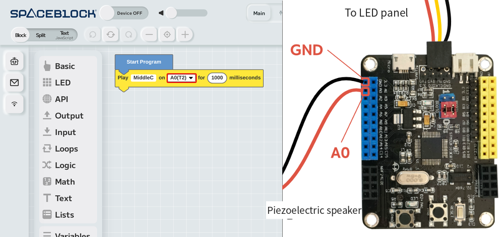
"GND" stands for "ground." When you connect an add-on part, always connect one jumper wire to "GND." Electricity flows from plus to minus, and "GND" is the minus side. It's needed to make a path for the electricity. It doesn't matter which "GND" you use, and you don't choose it in the program blocks.
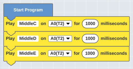
Leave the black jumper wire in "GND," move the red wire to "B0 (T3)" on the yellow pin socket, change the program to [Play (Middle C) on (B0 (T3)) for (1000) milliseconds], and run it. It works exactly the same way.
Add Sound to the "Okaeri" LED Sign
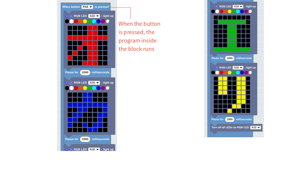
Let's add to the program so a sound plays with each character. As in the next picture, after each [RGB LED (A10): light up] block that shows a character, add a block that plays E, C, D, or G (mi, do, re, sol) for 1000 milliseconds. A character appears, the sound finishes, and then it moves on to the next character.
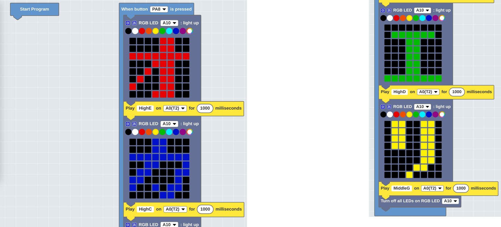
Now you have an LED sign that plays sounds. Let's watch it in the video. We added a sound effect that sounds like a door chime.
