
How to Use 3-Axis Gyro & Accelerometer Sensor Module
You can determine motion and orientation values by using the three-axis (X, Y, Z) gyro and acceleration sensor.
About the Component
As shown in the diagram, you can output values corresponding to the X-axis, Y-axis, and Z-axis in analog signals.
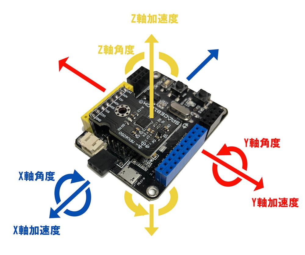
When the sensor is horizontal with the ground, the values will be near the following:
- X-axis angle: 0
- Y-axis angle: 0
- Z-axis angle: 180 (reversed, -180)
Changes and Confirmations Possible on the Sensor Side
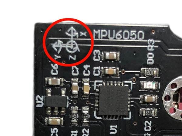
You can check the orientation of X, Y, and Z at the part marked with a red circle in the photo.
About I2C
I2C communication uses two signal lines, SDA and SCL. SDA stands for Serial Data and is the signal line for data. SCL stands for Serial Clock and is the signal line for the clock.
Specifications
| Voltage | 3~5V |
|---|---|
| Communication Method | I2C |
| Gyro Measurement Range | ±250 500 1000 2000 °/sec |
| Acceleration Measurement Range | ±2±4±8±16g |
| Size | 34 x 20 (mm) |
Connection
When Connecting Directly to the SPACEBLOCK Microcontroller Board
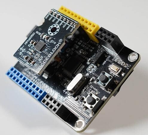
As shown in the photo, insert the pin header next to the yellow pin socket on the SPACEBLOCK microcontroller board into the pin socket of the three-axis gyro and three-axis acceleration sensor module.
When Connecting with Jumper Wires
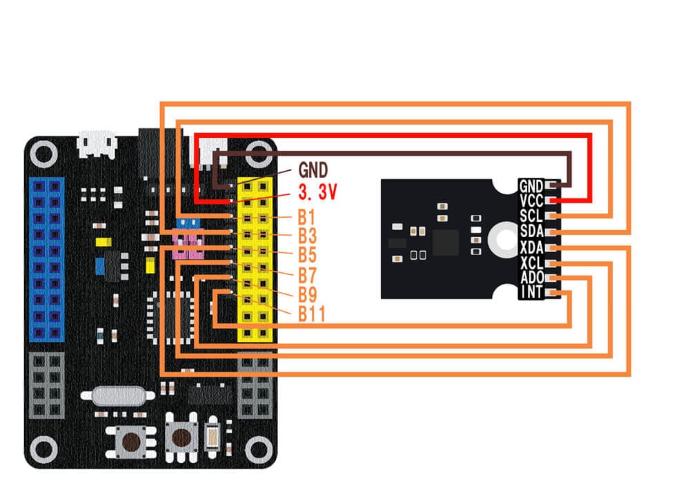
Connect the three-axis gyro and three-axis acceleration sensor module to the SPACEBLOCK microcontroller board using jumper wires (male-female) as follows:
- Connect the GND pin of the three-axis gyro and three-axis acceleration sensor to the GND pin of the SPACEBLOCK
- Connect the VCC pin of the three-axis gyro and three-axis acceleration sensor to the 3.3V pin of the SPACEBLOCK
- Connect the SCL pin of the three-axis gyro and three-axis acceleration sensor to the B1 pin of the SPACEBLOCK
- Connect the SDA pin of the three-axis gyro and three-axis acceleration sensor to the B3 pin of the SPACEBLOCK
- Connect the XDA pin of the three-axis gyro and three-axis acceleration sensor to the B5 pin of the SPACEBLOCK
- Connect the XCL pin of the three-axis gyro and three-axis acceleration sensor to the B7 pin of the SPACEBLOCK
- Connect the ADO pin of the three-axis gyro and three-axis acceleration sensor to the B9 pin of the SPACEBLOCK
- Connect the INT pin of the three-axis gyro and three-axis acceleration sensor to the B11 pin of the SPACEBLOCK
※ The pin header next to the yellow pin socket on the SPACEBLOCK microcontroller board can be treated as pins with the same signal as the adjacent yellow pin socket.
Usage
When using the block for reading gyro acceleration ~, it returns values for X-axis, Y-axis, and Z-axis respectively.
When using the block for reading gyro angle ~, it returns values for X-axis, Y-axis, and Z-axis respectively.
When using the block for checking if the gyro is moving, it returns whether each movement occurred in boolean (High(true) / Low(false)).
You can retrieve values from the three-axis gyro and three-axis acceleration sensor module using the block in the 'Input' category of your project.
For detailed usage of the block, click here.
Read gyro acceleration ~