
How to Use Infrared Obstacle Avoidance Sensor Module
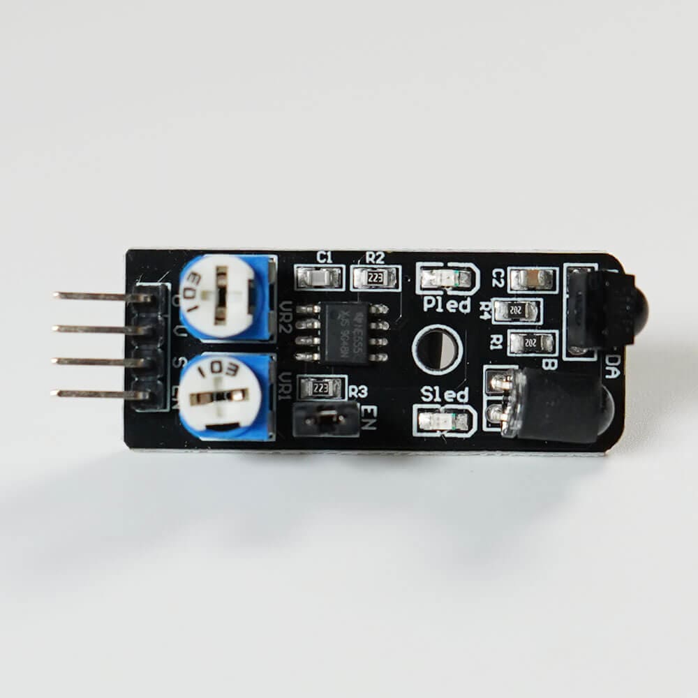
A sensor using infrared detects whether objects are nearby or not. It can be used for creating obstacle-avoiding robots, among other applications.
About the Component
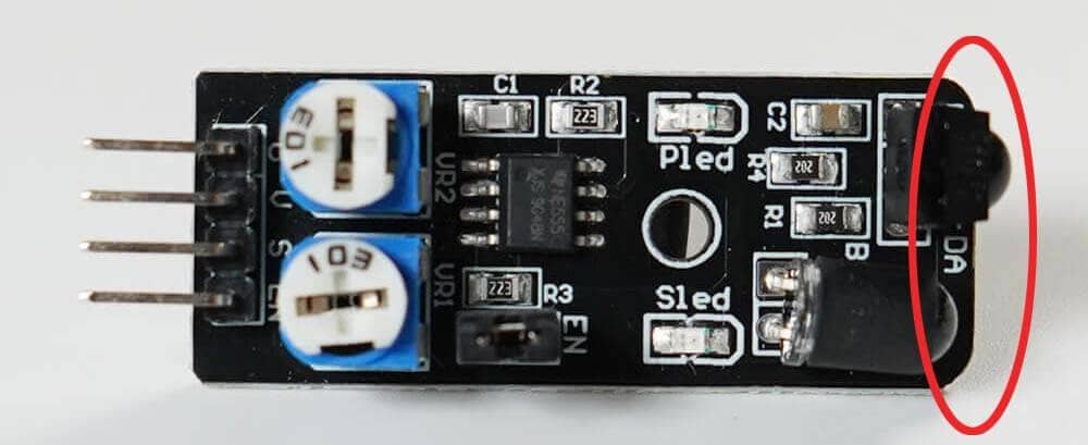
A sensor capable of transmitting and receiving infrared, marked with a red circle in the photo, outputs a digital signal (High(true) / Low(false)) indicating whether there is an obstacle in front of the sensor.
Changes and Confirmations Possible on the Sensor Side
When electricity flows through the sensor, the PLED (LED built into the sensor) lights up. When an obstacle is detected, the SLED (LED built into the sensor) lights up.
Additionally, you can adjust the detection distance by turning the potentiometer at the bottom of the component.
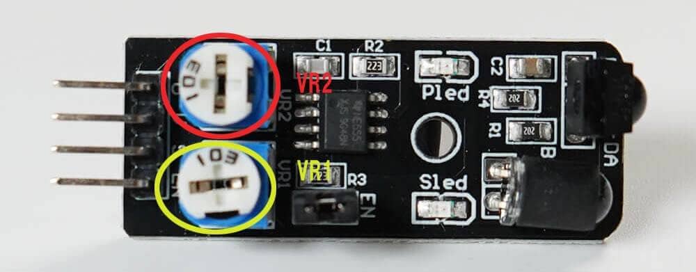
The potentiometer VR1 (yellow circular part) adjusts the infrared transmission. Turning it clockwise increases the detection distance, while counterclockwise decreases it.
The potentiometer VR2 (red circular part) adjusts the infrared reception. Turning it clockwise increases the detection distance, while counterclockwise decreases it. Adjust it only if fine-tuning is necessary.
※ Please adjust with care using a screwdriver. Excessive force or turning beyond the range can cause damage.
※ If you exceed the adjustment range, the sensor may constantly detect or not detect obstacles. In such cases, adjust it back in the opposite direction.
【Video: Adjusting the Infrared Obstacle Avoidance Sensor Module】
Adjusting the Detection Distance of the Infrared Obstacle Avoidance Sensor
Instructions for adjusting the detection distance of the infrared obstacle avoidance sensor
Preparation for Distance Adjustment
Checking the Current Detection Distance
Changing the Detection Distance
State of the sensor requiring adjustment
About the EN Pin
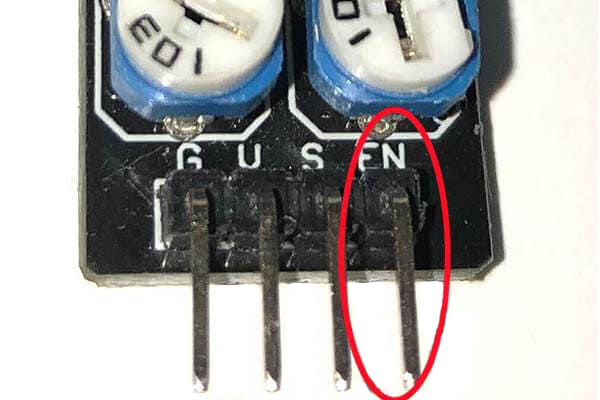
Normally, the EN pin does not need to be connected, but it can determine whether the sensor is enabled or not.
When the digital signal of the EN pin is High(true), the sensor is enabled; when it's Low(false), the sensor is forcibly disabled.
In the initial state (without connecting jumper wires), the sensor is enabled with High(true).
To change it, connect the EN pin to a digital pin on the SPACEBLOCK and then use the 'Digital Output' block to send High/Low signals to make changes.
Specifications
| Voltage | 5V |
|---|---|
| Output Signal | Digital |
| Detection Distance | 2〜40cm |
| Detection Angle | 35° |
| Temperature Range | -10~50℃ |
| Size | 45 x 16 (mm) |
Connection
Connect the infrared obstacle avoidance sensor module to the SPACEBLOCK microcontroller board using jumper wires (male-female) as follows:
- Connect the S pin of the infrared obstacle avoidance sensor to a digital pin on the SPACEBLOCK
- Connect the G pin of the infrared obstacle avoidance sensor to the GND of the SPACEBLOCK
- Connect the V pin of the infrared obstacle avoidance sensor to the 5V or 3.3V pin of the SPACEBLOCK
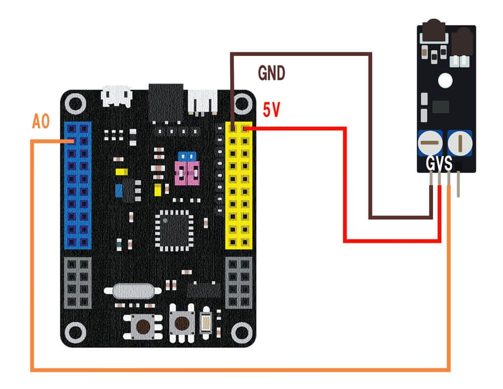
※ The image shows the signal line connected to pin A0. Digital compatible pins are A0 to A10, A13, A15, B0 to B15, and C14 to C1.
※ 5V, 3.3V, and GND can also be inserted into the pins with the same markings on the SPACEBLOCK microcontroller board.
Usage
If there is nothing in front of the sensor, it returns High(true); if there is an obstacle, it returns Low(false).
You can retrieve values from the infrared obstacle avoidance sensor module using the block in the 'Input' category of your project.
For detailed usage of the block, click here.
Digital Reading