How to Use Microphone Sensor Module

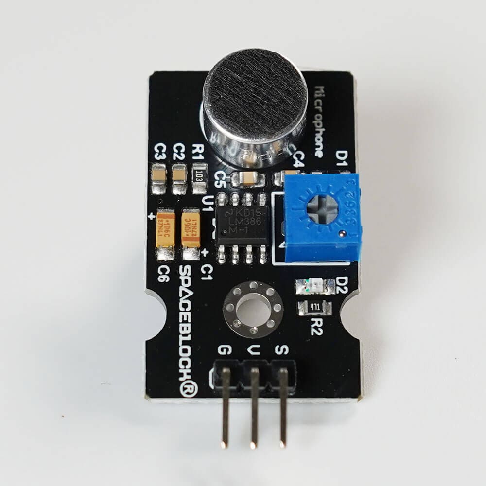
It measures the volume of sound. You can also create switches based on voice.
About the Module
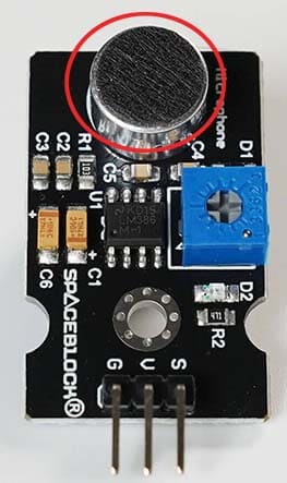
The sensor located in the red circle in the photo can receive the ambient volume of sound and output it as an analog signal (a number from 0 to 1023).

Things You Can Change or Check on the Sensor Side
If electricity is passing through the sensor, D2 (LED built into the sensor) will light up.
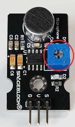
Also, by turning the potentiometer in the center of the module, you can adjust the sensitivity of the detected sound volume.

The potentiometer adjusts the sensitivity of the sound volume. Turning it clockwise increases the sensitivity of the detected volume, and turning it counterclockwise decreases the sensitivity.
※Please adjust it slowly with a screwdriver, etc. Since there is a limit to the range you can turn it, please be careful not to force it or apply strong force, as it may cause malfunction.
※If you exceed the adjustment range, the sensor may constantly detect or stop detecting. In that case, turn it back in the opposite direction and readjust.
Specifications
| Voltage | 3~5V |
|---|---|
| Output Signal | Analog |
| Size | 38 x 20 (mm) |
Connection
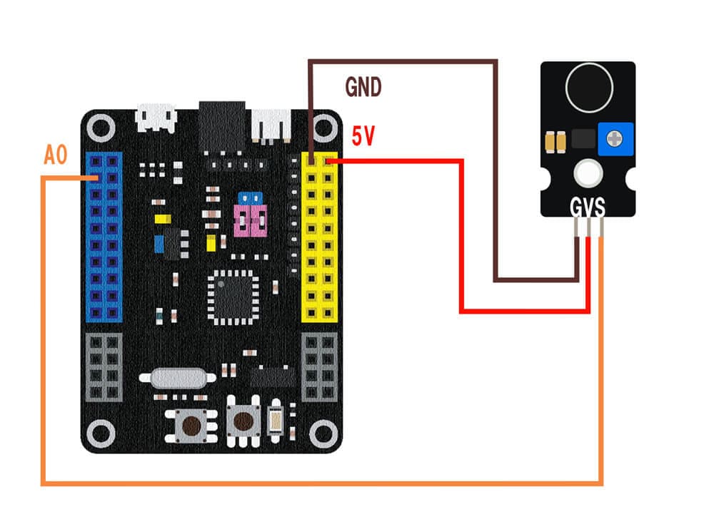
Connect the microphone sensor module to the SPACEBLOCK microcontroller board using jumper wires (male-female) as follows:
- Microphone sensor's S pin to SPACEBLOCK's analog compatible pin
- Microphone sensor's G pin to SPACEBLOCK's GND
- Microphone sensor's V pin to SPACEBLOCK's 5V or 3.3V

※The image shows the signal wire connected to pin A0. Analog compatible pins are A0 to A7, B0 to B1.
※5V, 3.3V, and GND can also be inserted into the pins with the same notation on the SPACEBLOCK microcontroller board.
Usage
The sensor detects the ambient volume of sound and returns a numerical value.
The larger the volume, the larger the number.
You can obtain values from the microphone sensor module using blocks in the 'Input' category of the project.
For detailed usage of the blocks, click here
Analog Read
